|
|
EVOLVE 3D |
|
|
EVOLVE 3D focuses on topography simulation; i.e., the evolution of features during deposition, etch, reflow, etc. processes. It is a "3D/3D" extension of the physics-based and chemistry-based "3D/2D" topography simulation tool EVOLVE that was released in the early 1990s. (Version 5.1 was released in 2000.)
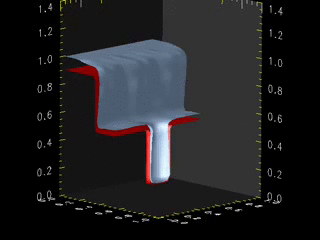
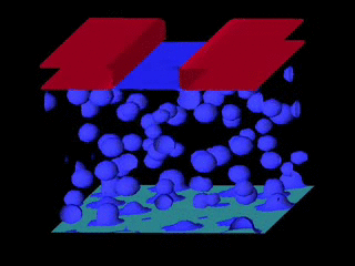
The clips shown on the right show the kind of things that can be done by EVOLVE 3D. The studies behind these clips were done using PLENTE, but EVOLVE 3D has replaced the topography evolution ability of PLENTE. The top clip shows a cut-away view of the via on an IC (being fabricated) via being filled with Cu (a simple ECD model). The bottom clip shows ion milling of porous material (with 30% porosity).
The capabilities of EVOLVE 3D are demonstrated in the left "clip" in the figures below as well throughout this process-evolution site. They are also demonstrated by numerous papers over the last 15 years; i.e., its capabilities are the same as other 3D/3D topography codes used by us as well as others. Feel free to contact PE with questions or suggestions.
EVOLVE 3D currently focuses on low pressure transport and reaction models. This is in part because solvers are widely available for systems for which "continuum" models are appropriate. It is also because we established the ballistic transport and reaction model, which has been adopted by most groups modeling low pressure processes. See EVOLVE for more information. However, we have interfaced EVOLVE and EVOLVE 3D evolution codes with those CFD/FEM codes, to allow more general evolution that those codes.
A few comments about EVOLVE 3D:
|
|
|
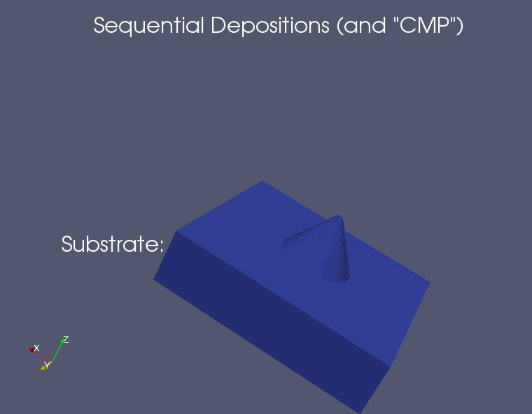
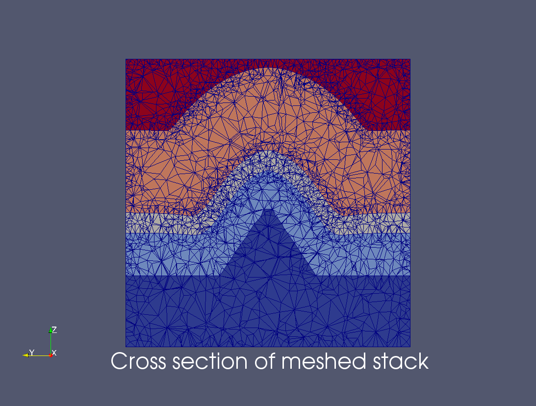
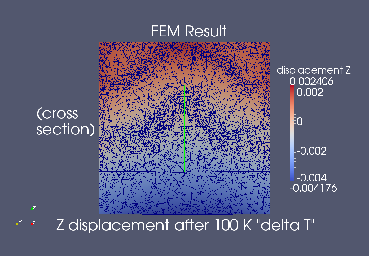
Physics-based process simulation and materials modeling: Nanostructure growth and finite element modeling (using Elmer)
The images shown above summarize how EVOLVE 3D can be used with other codes to predict the performance of structures based upon their fabrication details. The left image summarizes a set of depositions on a conical nanostructure (followed by planarization step). This multi-film stack is then meshed to generate a single volume mesh. The resulting structure is then put into Elmer, a finite element solver, for thermal-mechanical modeling. The right hand image shows the z displacements (on a cross section) after the temperature is raised by 100 K in the absence of displacements. Local unconstrained displacements depend upon position and upon the material of each layer.

PE Home
About PE
Contact PE
EVOLVE AMR
EVOLVE MM
EVOLVE 3D
EVOLVE
3D-ICs
PLENTE